
Gantry Crane Assembly and Disassembly Instructions
Introduction
These instructions were developed by Wallace Cranes with the goal of helping customers assemble and disassemble their gantry cranes.
We start with a quick overview so you can figure out what you’ll need to get started. Then we link to detailed assembly / disassembly instructions for each of our different crane models broken out by metal type and the shape of the tubing used in the crane frame (round, square or rectangular). These same instructions are accessible from the model pages listed on our main gantry crane product page.
Detailed printable and downloadable packets containing complete instructions for how to safely assemble, adjust, inspect, and operate your Wallace crane are also available here. These packets are usually shipped with your crane.
Assembly Overview
Wallace Cranes assemble easily with normal shop tools such as sockets, wrenches, screwdrivers (to attach safety tags and restraining pins) and hex wrenches. Most pin assemblies require no more than a 16 oz hammer so there is no need to force assembly.
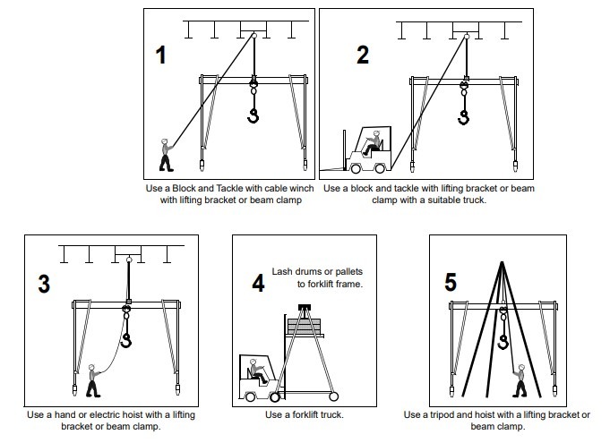
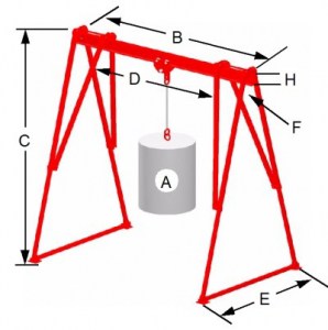
The TRICKIEST part of the assembly is the need to have the crane suspended so the legs can be attached to the I-beam. There are three recommended methods for suspending the crane. A forklift or overhead crane are the two most convenient options. The overhead crane will need to be tall enough to accommodate the fully extended legs of the crane you are assembling. A tripod is your third option. A tripod is great for assembling cranes in remote locations where you don’t have access to a forklift or overhead crane.
To ensure the safe operation of your Gantry, frequently inspect it for BENT, BROKEN, CORRODED, CRACKED, DAMAGED, or MISSING parts. DO NOT USE GANTRY if it does not meet inspection requirements. Please contact Wallace for replacements for any non-functional components.
Disassembly Overview
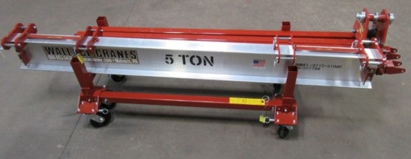
Wallace Cranes also disassemble easily to allow site-to-site or within-site movement. To help with moving disassembled cranes, we offer Kart Kits with caster frames and a support to securely hold parts during transportation. Note: there is no need to fully disassemble a crane to move it.
A 5-ton kart kit is shown below.
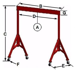
Leg Positioning
When setting up the crane, the legs should not be skewed. Legs should be positioned at 90° angles from the beam, as shown in the “from the ceiling” views below:
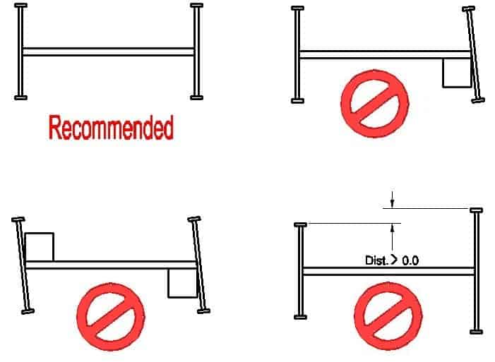
An exception to the last top-down view is when the crane is on an uneven surface. You may want a different leg height from end to end, but the beam should be level to prevent unwanted hoist travel.
Lifting Equipment and Rigging
A vital part of the lifting process is to be sure that all equipment has been inspected and is in good operating condition. For safe crane operation, the weakest link of the chain is a real consideration. As such, each piece of lift equipment (slings, lifting chains, hooks, lift bars, and similar components) must be inspected. These inspection procedures are detailed in the respective manufacturer’s installation and use instructions as well as within the applicable ANSI and OSHA standards. Some of these standards are listed in the following paragraph.
In addition to the inspection of the crane and lift equipment, you should also make sure the load is properly balanced. For example, when lifting pipes, you should make sure you have positioned the load so that it is centered in the sling and does not slip. Whenever lifting, employees should keep clear of suspended loads about to be lifted. Additional precautions are spelled out in OSHA 29 C. F. R. 1929 Safety and Regulations and the rigging equipment manufacturer’s recommendations.
Other lifting standards that may apply are ANSI B30.16-1987 for Overhead Hoists (Underhung) and ANSI B30. 11-1988 Monorails and Underhung Cranes.
Detailed Assembly / Disassembly Instructions
View and/or print detailed instructions (PDF) for how to assemble and disassemble each of our gantry cranes. Instruction packets are provided below broken out by fixed and adjustable height models, metal type, and lifting capacity. “Round,” “square,” and “rectangular” refers to the shape of the metal used in the gantry frame.
Fixed Height Model Steel – N/A
Fixed Height Model Aluminum – N/A
Adjustable Height Model Steel
- 1, 2, 3 & 5-ton round (Form 429)
- 3, 5, 8 & 10-ton square (Form 411)
Adjustable Height Model Aluminum
- ½ – 3-ton round (Form 429)
Adjustable Height Model Hybrid (Steel Tube Aluminum I-Beam)
- 1, 2, 3 & 5 ton square (Form 411)
Fixed Height Model Steel
- 1 – 7 ½ ton rectangular (Form 218)
Fixed Height Model Aluminum
- 1 & 2 ton rectangular (Form 218)
Adjustable Height Model Steel
- 1 – 7 ½ ton rectangular (Forms 386 and 387)
Adjustable Height Model Aluminum
- 1 & 2 ton rectangular (Forms 386 and 387)
Adjustable Height Model Hybrid (Steel Tube Aluminum I-Beam) – N/A
Fixed Height Model Steel
- 1, 2, 3 & 5 ton square (Form 449)
Fixed Height Model Aluminum – N/A
Adjustable Height Model Steel – N/A
Adjustable Height Model Aluminum – N/A
Adjustable Height Model Hybrid (Steel Tube Aluminum I-Beam) – N/A
Fixed Height Model Steel – N/A
Fixed Height Model Aluminum – N/A
Adjustable Height Model Steel
- 500 – 1000 lbs square (Form Mite)
Adjustable Height Model Aluminum – N/A
Adjustable Height Model Hybrid (Steel Tube Aluminum I-Beam) – N/A
Fixed Height Model Steel
- 15-ton square (Form 15T)
Fixed Height Model Aluminum – N/A
Adjustable Height Model Steel – N/A
Adjustable Height Model Aluminum – N/A
Adjustable Height Model Hybrid (Steel Tube Aluminum I-Beam) – N/A