
Tri-Adjustable Operating, Adjustment & Inspection Instructions
(Form 379)
Read, understand, and comply with all instructions supplied with your crane. Also, pay attention to the equipment used with the crane such as hoists, trolleys, power drives (if applicable). Read, understand, and comply with the requirements of OSHA (Occupational Safety, and Health Administration) 1910.179.
Assembly and Safety Instructions
Inspect Crane Before Moving and/or Each Day’s Use
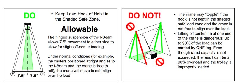
- Center load under i-beam before lifting.
- When moving the crane under load, position the load at the center of the i-beam.
- Use the crane at the lowest height possible to lower the center of gravity.
- DO NOT lift or support humans.
- DO NOT allow the load to swing or roll against any supporting members.
- DO NOT TOW or pull the crane.
- DO NOT OVERLOAD THE CRANE.
- Do not lift loads that are heavier than the rated capacity of the crane.
- Make certain the load is free to be lifted.
Positioning of Crane to Handle Loads
Positioning of Casters
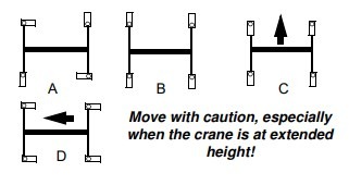
A. To secure crane position while lifting load, lock diagonally opposite casters as shown.
B. To utilize maximum crane strength, lock the casters as shown.
C. To move the crane and/or load it perpendicular to the i-beam, lock casters as shown or allow casters to pivot freely.
D. To move the crane and/or load it parallel to the i-beam, lock casters as shown or allow casters to pivot freely.
Adjustment Instructions
Height Adjustment Procedure
- Lock casters parallel to the I-beam to prevent the main support legs from moving during adjustment.
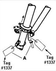
- Locate safety stop pins, as required during adjustment. See instructions on Tag #1337 attached to the safety stop pin.
- Raise crane slightly to clear notches in load bolts, pull out load bolts, and rotate 90° to the “lock-out” position.
- When within approximately 3″ of the desired height, rotate load bolts to the “unlocked” position.
- Continue height adjustment (up or down), to allow load bolts to align with and engage the next hole.
- Visually check to ensure all four load bolt caps are FULLY ENGAGED.
- Insert safety stop pins with Tag #1337 into the first hole below the upper main legs and secure them in place with locking pins. When the crane is at minimum height, attach to brace leg, as shown in Illustration “A”.
- Remove crane supports, trolley and hoist stops, and adjust caster positions as required.
Caster Frame Adjustment Procedure
- When the i-beam is supported externally, raise the i-beam slightly to take the weight off the caster frame spread adjustment pin. Remove the pin. Raise or lower the i-beam to decrease/increase caster frame spread. Replace spread adjustment pins. Secure in place using locking pins.OR
- a) Turn and lock casters perpendicular to the i-beam and secure the trolley and hoist to prevent rolling.
b) One jack (right or left) only is used for caster frame spread adjustment.
c) Remove the pulley at the bottom of the jack and pass the end of the cable through the pulley slot and extend it to the first hole in the main leg above the caster frame using the eyebolt provided. Reinstall pulley, axle, and klik-pins.
d) Insert pin assembly and jack into the first hole above the caster frame; attach all the locking pins in the pin assembly.
e) Using a jack winch, take the weight off the caster frame adjusting the pin, then remove the pin.
f) Adjust spread as required and replace adjusting pins. Secure using locking pins.OR - When the lever-type winch is used, take the weight off the spread adjustment pin, then remove the pin. Adjust spread as required and replace spread adjustment pins. Secure in place using locking pins.
NOTE: Be prepared to control the weight. The caster frame tends to open to maximum spread when the spread adjustment pins are removed.
Cantilever Configuration/Adjustment of Distance Between Legs Along Length of I-Beam Procedure
- Raise one end of the I-beam until casters are off the floor.
- Loosen set screws on top of I-beam hardware.
- Slide I-beam hardware, with legs attached, on I-beam until the desired amount of cantilever or leg adjustment is achieved.
- When adjusting for the cantilever, DO NOT OVER-ADJUST. Adhere to distances specified in Form 123 (Cantilever Chart provided with the crane) for the amount of cantilever, load and counterweight required.
- When the desired amount of cantilever or leg adjustment is achieved, securely tighten set screws to prevent movement.
- Repeat above if leg adjustment on the opposite end is required.
Wallace Built-In Safety
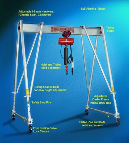
Read, understand, and comply with the instructions on the crane and:
A. Rated load clearly stenciled on opposite sides of I-beam.
B. Form 379 (This Form) is attached in a convenient location by user.
C. Caution label for instructions attached to caster frames.
D. Caution label pointing to caster frame adjustment pin.
E. Caution labels attached to main legs.
F. Caution tag attached to safety stops.
G. Caution tag attached to locking pins.

CAUTION AREAS
Make certain that all CAUTION labels are in place and legible. Replacements for damaged or missing labels are available upon request.
Inspect that rated capacity is plainly marked on each side of the I-beam. Each hoisting unit shall have its rated load clearly marked and shall be legible from the ground or floor.
Inspect safety cables in caster frames for proper attachment, fraying, or damage. Replace damaged cables immediately.
Tri-Adjustable Visual Checkpoints
To ensure the safe operation of your crane, inspect it for bent, broken, worn, corroded, cracked, or missing parts. A series of vital checkpoints are described and shown below. Check these areas closely to ensure that all pins and fastening hardware are in place and securely attached. Caution Tags are attached to the Locking Rings and Locking Pins in these critical areas to aid in your inspection. DO NOT USE the crane if it does not meet these and the relevant ANSI B30.17 inspection requirements.
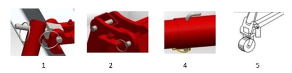
- Brace legs are attached to pin assemblies and secured with locking rings. On round tube models (shown above) the flat end of the brace leg is attached to the load bolt casting. Also, be sure the load bolt is properly engaged. (See number 3 below.)
- The main legs are attached to the pin assemblies and secured with locking rings. Locking rings at each end of the I-Beam should be in place and secured to ensure the I-Beam Hardware never slides beyond the end of the i-beam.
- The four safety stop pins must be installed and secured with Klik pins in the first hole below the load bolt. (See large blue crane image above with the “Wallace Built-In Safety” heading.) When the crane is at minimum height, attach pins to the brace leg.
- The caster frame spread pins should be secured with Klik pins.
- Lower main legs are attached to the caster frame casting with pins, secured with a Klik pin. Inspect casters and wheels for damage, such as cracks, bent king pins, and freedom of movement. Replace any damaged casters immediately.
General Safety Instructions for Crane Adjustments
- ADJUSTMENTS and/or repairs should be made in an area where they will have the least interference with ongoing operations.
- DO NOT make adjustments when the crane is under load. If the crane is in operation, lower and disconnect the load before making any adjustments.
- SECURE TROLLEY AND HOIST to prevent movement during adjustment of the crane.
- EXTEND CASTER FRAMES to maximum width (last hole) when possible, for the greatest stability.
- SAFETY STOP PINS should be installed in the first hole below the load bolt on the main legs.
- DO NOT ADJUST any one leg (or end) more than one foot above or below the other legs (or end), as it could cause the crane to “topple” and result in injury and/or equipment damage.
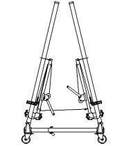
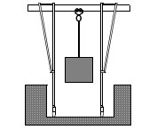
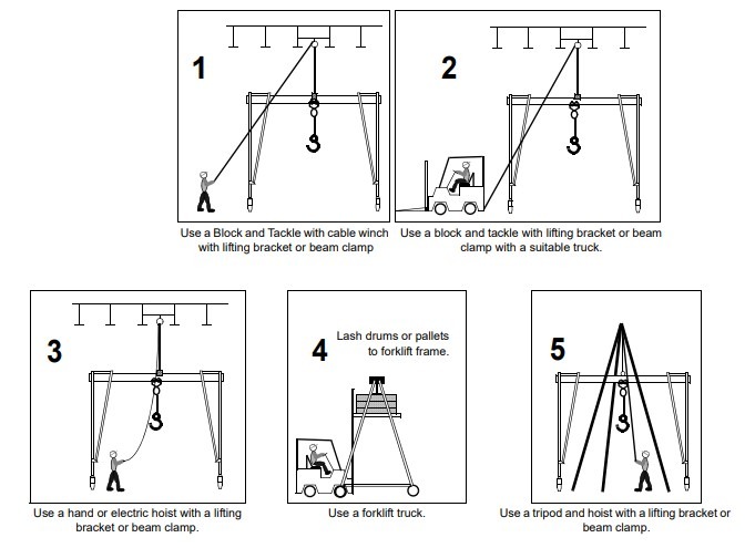
Methods of Supporting Crane for Assembly
DO NOT ASSEMBLE, DISASSEMBLE OR MAKE ANY ADJUSTMENTS TO CRANE UNTIL the unit is supported by one of the five methods illustrated below.
NOTE: A PDF version of this document can be printed or downloaded here.